
 Principle of PTZ Hall Sensor
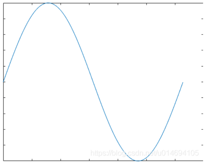
The gimbal motor generally follows a small magnet, and this sticker is divided into NS poles. For the Hall sensor, we take OH49E as an example. It outputs data of different sizes according to different magnetic fields. If the Hall sensor is placed near a magnet, the output of the Hall sensor is similar to a sine wave when the magnet rotates once:
 From the waveform, we can see that the magnet rotates once, and the output of the sensor can represent two angles with the same value, which obviously cannot meet our requirements, so we add one more Hall, which is 90° with the first Hall. Quadrature, its output waveform is as follows:
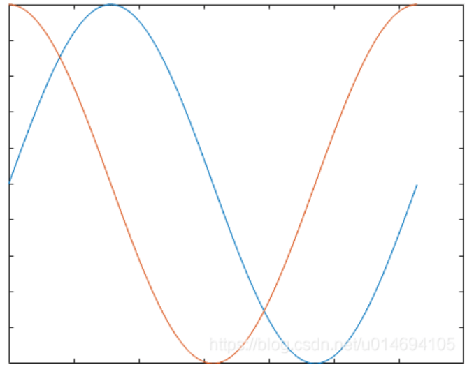
In the figure, the two Hall sensors output orthogonal sine waveforms. After certain processing is performed on them, one-to-one correspondence between angles and waveforms can be realized. The formula is as follows:
y=atan(x1/x2);
y can represent the electrical angle of the motor.
·In fact, there is another problem to be solved:
That is, the amplitude of the sine wave is not from 0 to 1. It may be from 800 to 5000. I am just an example, the specific number varies with different magnets. Therefore, it is necessary to normalize the waveform amplitude before calculating the angle, and the maximum and minimum values of the sensor must be measured before the normalization.
My method of measuring the maximum and minimum values of the Hall is to rotate the motor one circle, and then collect the maximum and minimum values of the Hall data.
Excerpted and translated from the following link https://blog.csdn.net/u014694105/article/details/105053091